Heat and temperature changes are major challenges in electronics design—especially as devices become smaller, faster, and more complex. As an electronics engineer, it’s crucial for your design’s performance to understand how it reacts to temperature variations
* The offer is completely non-binding and free, covering one specific design from your company. Accepting the offer does not commit you to purchasing Nordcad’s solutions.
Free and Non-Binding
Step #1
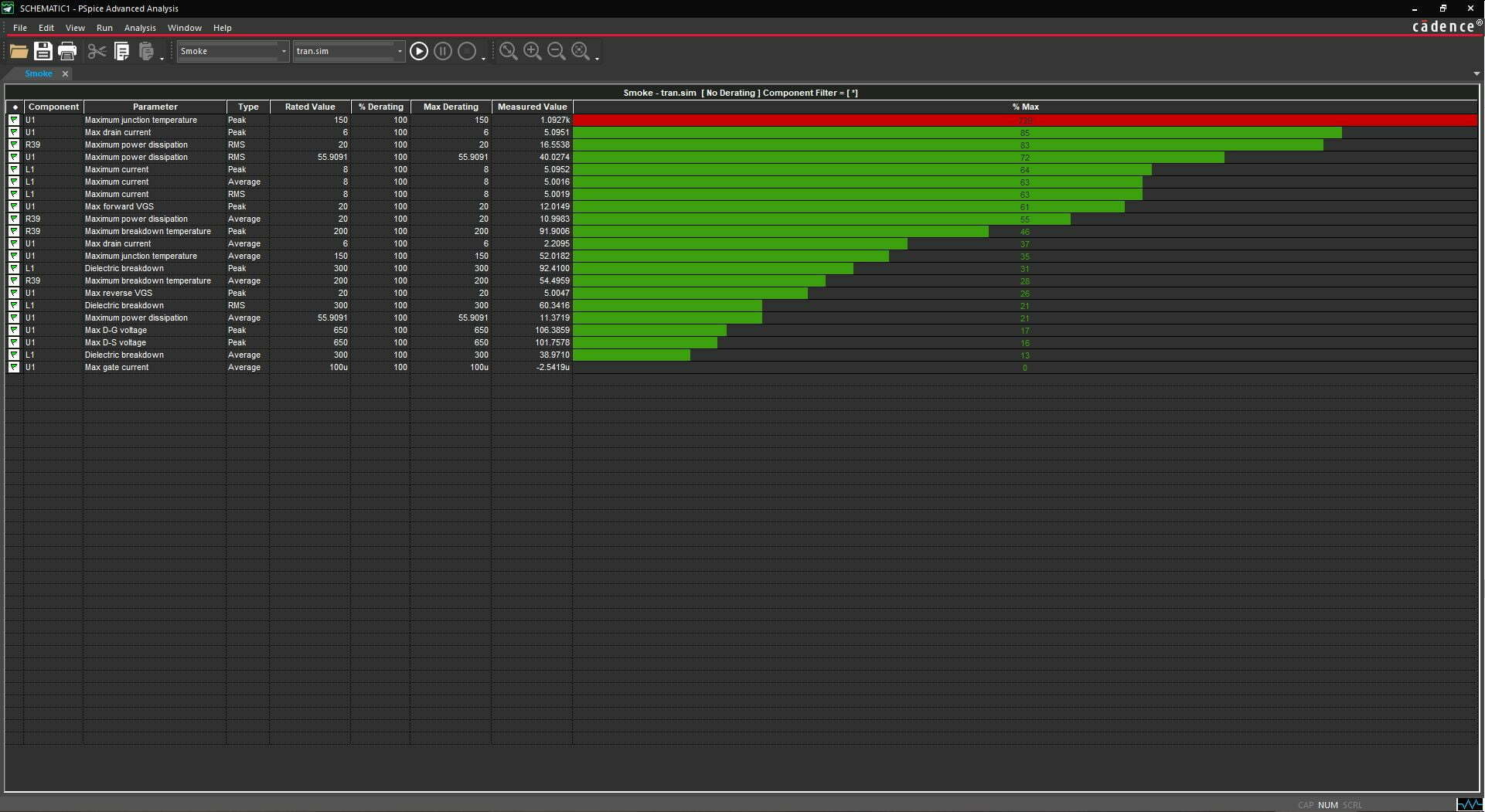
Before looking at the PCB, it’s a good idea to simulate your schematic/diagram with a smoke analysis using a tool like PSpice.
A smoke analysis tests that all components in your circuit function correctly and safely during operation. This analysis examines how your components react to temperature, current, power, and voltage changes.
Step #2
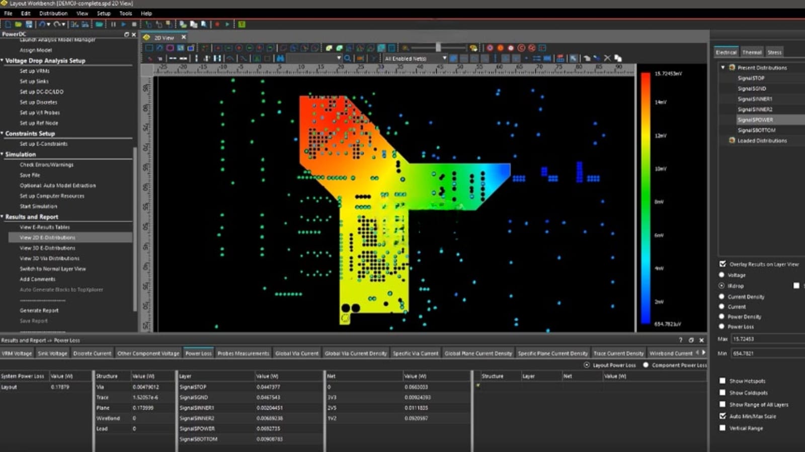
Once the schematic is finalized, the next step is to analyze the PCB using Finite Element Analysis, Computational Fluid Dynamics analysis, or both — depending on the need.
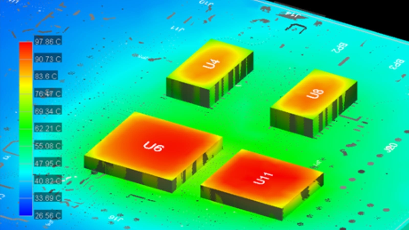
Analysis/simulation focusing on solid materials (solids) using 2D/3D FEA analysis. Heat dissipation into the air is simplified.
The tool is used at the PCB level.
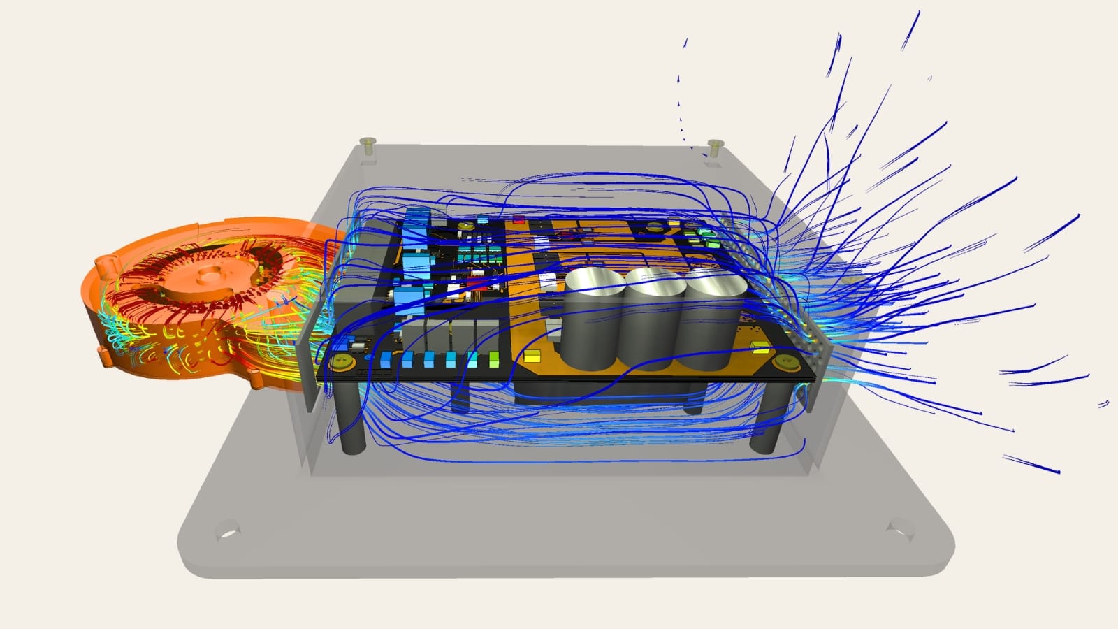
Analysis/simulation focusing on airflow using 3D CFD analysis. Here, the simulation of solid materials is simplified.
The tool is used at the PCB level.
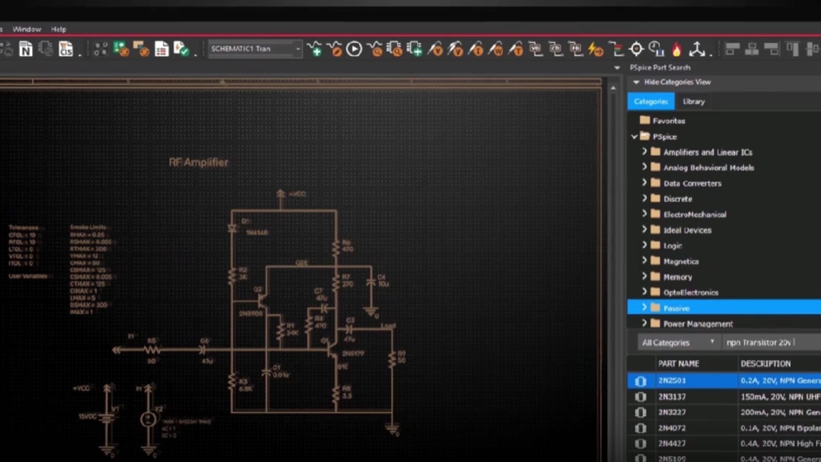
Simulation at the schematic level to prevent costly errors and ensure the quality of the final product.
The tool is used at the schematic level.
Free and Non-Binding
